Read here what we learned while fixing the focussing mechanism of a Meade 14'' f/10 Schmidt-Cassegrain telescope. We hope it may be helpful in case you have similar trouble.
Based on the experience of Harry Balster and Marc Fokker, AKN
Our focusing mechanism got jammed...
We were confronted with a basically pristine LX200 14'' SCT. Unfortunatly, it had become useless because the focussing mechanism had completely run stuck. There was no way of moving the mirror lock knob to dissengage the clutch or shift the mirror position with the focus knob. In fact, we even didn't know in which position the mirror was, and in which direction the knobs were turned before everything got stuck. This can be the trouble with telescopes that are used by many people. As you can imagine, nobody left a note claiming this achievement...
|
|
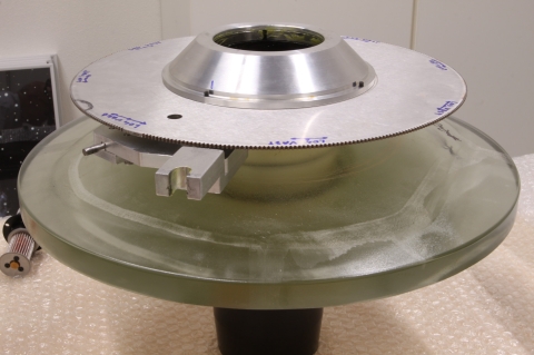
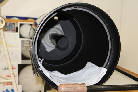
At the left hand picture (figure 1) you see the contraption consisting of the primary mirror, together with the main parts of the mirror lock mechanism and parts of the focusing mechanism. The lower large disk is the mirror. Everthing here is standing upside down. The construction is standing on a black tube that -when completely assembled- would slide around a tube inside the OTA. The inner tube (visible in figure 5) is firmly screwed into the back of the OTA, and secured with 'lock tight'. The focusing knob drives a long screw (figure 7) with a transversal drilled hole at the end. The round pin poking to the left in the picture fits the drilled hole in the focusing screw. By turning the screw with the focus knob, this complete contraption would slide over the baffle. That is, as long as it is free to move. Locking the mirror is done by the gear/pinion construction. The pinion is visible in the next image, figure 2. The gear is the tapered shaped disk, also visible at the top of figure 1. It is screwed on the the same black tube that carries the mirror and focus pin. Between the black tube and the gear fits an almost round spring with tapered shaped edges that both fit the similar edges of the gear and black tube. The open part of the spring is just visible, together with patches of grease at the inside of the gear. When the gear is turned clockwise, its tapered shape inside will press the spring firmly around the inner tube. The result is a firm grip of the spring on both the inner and outer tube. |
|
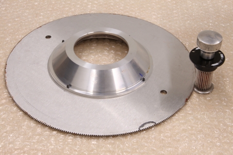
Here above, in figure 1, poking towards you, you 'll notice a small fork shaped form made in thick aluminium. This fork slides over a aluminium strip inside the OTA. It's purpose is to inhibit rotation of the above contrapion around the inner baffle when engaging or disengaging the mirror lock. In figure 2 you can notice a part of the gear without teeth, at the right hand side, in line with the two small holes. It's purpose is to inhibit to screw the gear loose from the black tube. Something that Jerry Wise seemed to have found in his telescope. As I earlier said, our trouble was the opposite. What we found out after dismanteling the corrector and primary was that the primary mirror was moved by the focus knob up toward the primary in its most extreme position. The result was high mechanical tension from the gear to the flange of the pinion. I suspect it must have been hard to tell the difference in which direction to turn. I doubt, people could turn further in the wrong direction. Anyhow, the result were damaged teeth on the pinion and a gear that didn't want to loosen itself. Another part of the cause of our trouble were small metal pieces, left over from drilling into the back of the OTA. A small modification had been done to the OTA to attach extra counter weights. Apparantly, it was to much trouble to do a proper job and remove the mess at the inside. We found aluminium thrash on many places in the OTA, especially in on the parts covered with grease. The good part was that the primary miror survived that job with only one minor scratch. |
|
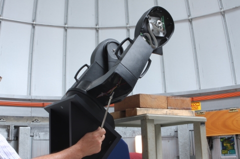
Taking the OTA from the forkFirst of all, keep in mind that this telecope is an american design. Use the proper tools (English/imperial sized hex keys and torx) for the screws! Make sure you've got tools that fit the screws before starting. Another important thing: take pictures of the position of three screws and the pin between two of the screws on each side of the OTA near the declination axis. When you reassemble the OTA, you must put it back with both pins in their same positions to keep the orthogonal allignment of your OTA in the fork. The way we did it: Taking the tube from the mount is at least a two person job. Do some scaffolding to give a secure support of the OTA in the fork. Have a strong person holding the OTA in place while the second quickly removes the 2 x 3 screws from the sides near the declination axis of the OTA. You 'll need to tilt the OTA in declination a little to reach for all screws. Then, loosen the large screws on the bottom of the fork (figure 3) as much as needed to the give some space to remove the OTA. For the time you let the OTA out of the fork thou shalt not place any of your six screws in back in the OTA. Without the material of the fork in place the screws are long enough to reach into the path of travel of your primary mirror, with disaster as a result!
|
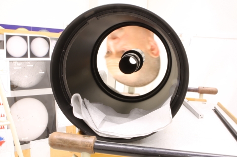
Removing the correctorFigure 4 shows you the primary miror in the OTA. To remove the corrector plate, we first removed the ring that holds the corrector in place. After that, we made a hook like tool from epoxy circuit board. This tool must be small enough to slide through the two cut-outs in the ring that carries the corrector in the OTA. One of the cut-outs is visible in figure 4, a little left from the top. A little playing with small bits of pressure from the sides and a little pulling with the hooked tool made the corrector pop out unharmed. Do not use metal tools for this!
Removing the primary and focus lockBecause of our problem, we hardly could slide the primary and the mirror lock mechanism over the tube. At the side of the rear of the OTA, there are two screws close together that seem to keep a piece of plastic in place. What they do in fact is keeping an aluminium strip inside the OTA in place that guides the fork shaped part visble at the right of figure 1. We set the screws a little loose by only one or two turns. If you remove them both entirely, the aluminium strip will drop in the OTA! You obviously don't want do that, it might damage the mirror and you only can put the strip back after removing the primary. By loosening up the two screws a bit, we were able to rotate the mirror a few degrees around the inner tube by turning the mirror lock knob. On second thoughts, it was probably easier the dismantle the mount with OTA completely from the pier, put the OTA on its back and remove the six screws from the side and loosening the fork on a side. When you move the OTA, it may be wise to keep the primary lower than the secondary. Otherwise, when your problem is a loose focussing mechanism, it is at least theoretically possible that your primary slides of the inner baffle into the corrector. Ouch! |
|
|
I reached inside the OTA and grabed the outer tube firmly while Harry turned the mirror lock knob back and forth. While pulling, I could move the mirror a little towards me. Soon movement was limited by the flange of the side of the pinion. After removing the miror lock knob from the back, I could pull the whole contraption a little further. The front part of the inner tube is a little wider. Usually the mirror will not slide on this part of the tube while focussing. In our situation with the stuck mirror lock it was very hard to slide it over this part. I 'll keep the language for my self that I thought of while pulling and turning. Figure 5 shows you the inner tube in the center. This baffle is screwed in the back of the OTA, with plenty lock tight used. On this baffle slides the black outer tube visible in figure 1, together with the primary mirror and mirror lock mechanism when you turn the focus knob. We thought of screwing the inner tube loose from the OTA together with the primary and focus lock on it. We didn't find a way to do this that would not result in damage. There must be loads of lock tight between tube and OTA. Beside of that, if we succeeded, I suspect we couldn't get the contraption out the tube without removing the front of the OTA because of the length of the inner tube. Removing the front or back is a bad idea, because these seem to be glued to the tube. |
|
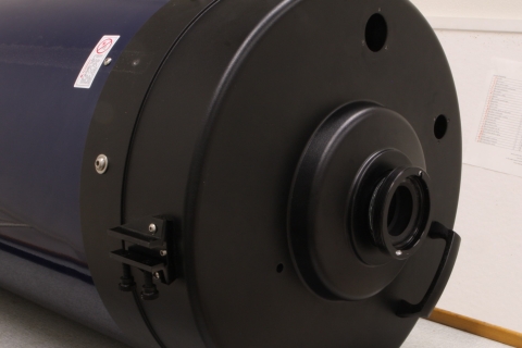
In figure 6 you 'll find the back with all knobs removed. There 's a small hole that is ususally filled with a plastic plug as a dust cover. This is the place were the transport bolt must have been when the instrument was shiped to you. Now it may be useful to do a rude measurement of the position of the mirror. Note that depending on the position of the mirror lock gear, one of the two holes in the gear can get lined up with the hole in the back.
|
|
|
|
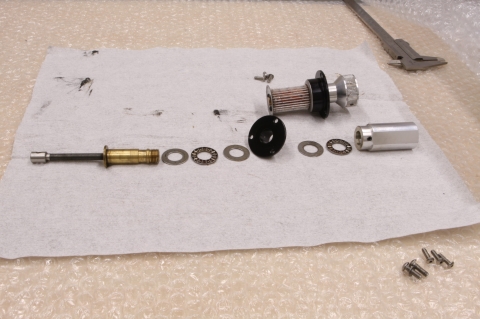
Figure 7 at the left, shows you the focus screw and its parts. By turning the knob fixed to the brass nut, the stainless steel screw pushes or draws the mirror along the baffle. The focusing pin in figure 1 fits the hole (hardly visible here) at the left end of the stainless screw. Note that the black bushing needs to be placed with the tubed part in the back of the OTA. When you do it reversed, you won't be able to get the the primary in the position for a useful focus. In that case, the focal point will be found inside the baffle, close to the end of the OTA. In the picture, one of the washers, the one between the bearing and the knob at the right, isn't shown in this picture. |
|
Sources of information that were helpful for us: Jerry Wise's article Our telescope is identical, he only had the opposite trouble. Greg Nowell's article Good pictures of a smaller sct that prove it can be child's play. MAPUG astronomy topical archive on LX200 mirror shift and focusing issues. |
|